HELP for CRCN GUI
Copyright:
http://www.mtu.edu
1. Simulation Process Tutorial
1.2 Generate a topology and traffic file
2 Simulation Environment Setting
3. Random Topology/Traffic Generators
1. Simulation Process Tutorial
1.1 Simulation Process
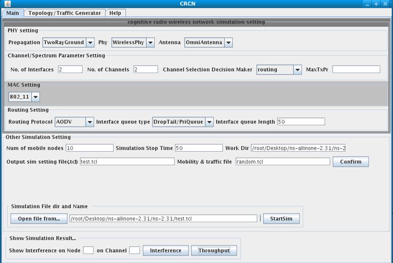
Under main tab as shown in the following figure,
Step 1: Select the simulation setting in the corresponding PHY/Channel/Spectrum Parameters/MAC/Routing setting. For the user defined Routing and MAC protocols, several default names such as Mac3/Routing1/Routing2 are reserved for the user defined protocols in the GUI. Users only need to use these names for their MAC or Routing protocols.
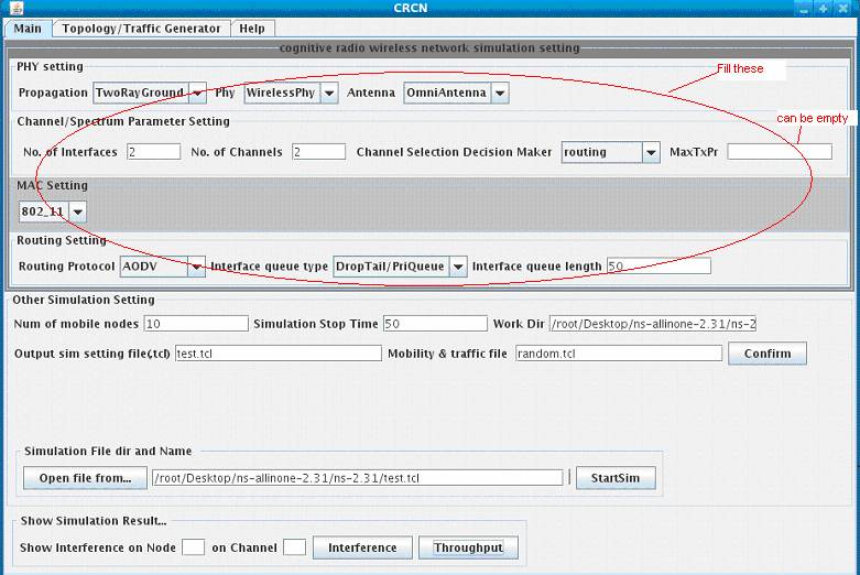
Step 2: Under Other Simulation Setting, define or specify the number of nodes, simulation stop time, and mobility and traffic file. Then specify the ns working directory in Work Dir and file name of the simulation script in Output sim setting file. The traffic and mobility file can be generated under Topology /Traffic Generator tab. The traffic and mobility file will be stored under the Work dir. After click “Confirm” button,
the simulation script will be generated under the Work dir.
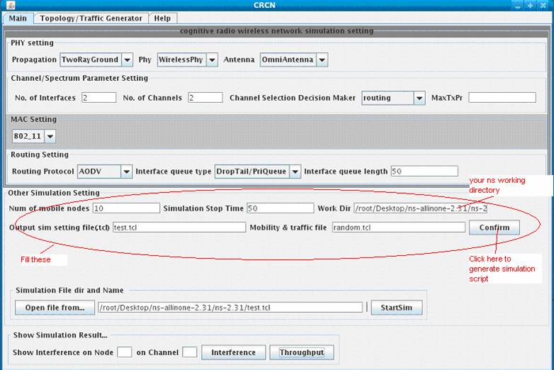
Step3:Under Simulation File dir and Name, choose a simulation script from “Open file from…”, or just type in the simulation file with directory as shown in the following figure, then click “StartSim”, which starts the simulation process. When the simulation is ongoing, the “StartSim” will have a darker color.

Step4: After the simulation finish, click the Interference or Throughput button, then you can see the simulation result.
1.2 Generate a topology and traffic file
This GUI is incorporated the topology and traffic generator provided by NS2. Please note that the topology and traffic file are written into directory specified by Work Dir.
Step1:
Under Random Topology Generator,
fill in the parameters for defining the topology and mobility model. The Work
Dir under the “Main” tab should
be changed to your ns directory.
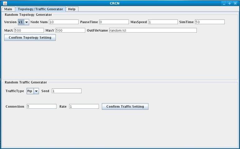
Click “Confirm Topology Setting” once you finish.
Step2: Under Random Traffic Generator, fill in the parameters required to generate the traffic, and then click “Confirm Traffic Setting”. The topology and traffic file is generated onto the directory specified by Work Dir. They are merged into the same file.
2 Simulation Environment Setting
This GUI provides the cognitive wireless simulation selection based on the wireless simulation TCL script for NS-2 [1].
2.1 Physical Layer Setting
A. Physical Layer
Under PHY setting, several options are provided to configure the wireless physical layer.
Propagation
There are
several selections for Propagation: TwoRayGround/FreeSpace.
Antenna
The default selection is OmniAntenna, which is the only supported antenna type in NS2. Option is provided here for future extension.
|
The above
options are equivalent to the following code in TCL simulation script: |
|
#Define Options set val(prop) Propagation/TwoRayGround ;# radio-propagation model set val(ant) Antenna/OmniAntenna ;# antenna model |
B.
Channel/Spectrum Parameter Setting
This section defines the number of interfaces per node and number of channels in the network.
No. of Interfaces:
This field indicates the number of interfaces per node. Default is 1 interface for each node. When this field is larger than 1, the field No. of Channels should be set value equal or larger than the value of No. of Interfaces.
No. of
Channels:
This field indicates the number of channels to use in the network.
This section defines some spectrum parameter setting.
Channel Decision Maker:
The option routing means the multi-channels are only
visible to routing layer. The option routing/DSA means the multi-channels are
visible to both routing and
MaxTxPr:
This field defines the maximum
transmission power for the Dynamic Spectrum Access algorithm. NS
There is no equivalence to the TCL simulation script for MaxTxPr options.
2.2 MAC layer Setting
Several
Mac3 can be
replaced by users’ new
The detail TCL
setting for CR
2.3 Routing Setting
Routing
Protocol
The routing protocol selection includes AODV/DSR/WCETT[1].
Interface queue type
It has two options DropTail/PriQueue,
Interface queue length
This length can be variable. Default is 50.
Routing1 and Routing2 can be replaced by users’ new routing protocol.
The detail TCL setting for CR Routing can be referred to this link.
2.4 Other Simulation Setting
No. of mobile nodes
This field indicates the number of mobile nodes in the simulation scenarios. Please note that this number should be consistent with the number defined in topology and traffic file.
Simulation Stop Time
This field indicates the time when simulation stops.
It is the current NS working directory: XXX/ns-allinone-2.31/ns-2.31. All tcl files generated by this GUI will be stored under this directory.
This
field saves the simulation setting file into a .tcl file. This simulation file
will append with the topology and traffic file defined by user when the confirm
button is clicked. After the file appending
action, the complete simulation file has the same name. This file
will be generated under the directory specified by Work dir.
Mobility & Traffic file
This field specifies the location of
topology and traffic file. User can provide topology and location file or
generate it under Topology/Traffic
Generator. This topology and traffic file will be appended to the
final executable file, whose name is given in Output
sim setting file(.tcl).
This field selects the simulation file. The simulation file can be the one provided by the user or generated through the confirm action.
2.5 Simulation Result
When this
button is pressed, a figure will pop up showing the interference information on
the selected node and channel, which are selected in the fields of Show
interference on Node and On
Channel.
Note: When only one channel or one radio is defined, there
is no interference information recorded for this situation. Hence, there will
be no figure showing up for single channel network scenario.
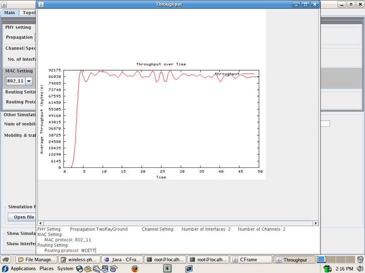
When this button is clicked, the end to end throughput will display.
3. Random Topology/Traffic Generators
The Topology/Traffic Generator incorporated in this GUI is described in the NS2 tutorial [2], which is a component released with NS-2.
3.1 Random Topology Generator
Version
This selection contains V1 and V2.
Node Num
This field defines the number of nodes that have topology and movement information.
PauseTime
This field indicates the average pause between movements.
MaxSpeed
This field indicates maximum moving speed of a node.
SimTime
This field defines the simulation stop time.
MaxX
It defines the maximum X coordinates among all the nodes.
MaxY
It defines the maximum Y coordinates among all the nodes.
OutFileName
It defines the output directory and topology file name, which will be used by in the main window. It should be in the same directory as the Workdir.
Workdir
It tells this GUI the working directory of NS-2.
3.2 Random Traffic Generator
TafficType
It has two traffic types: CBR and TCP.
Seed
The seed value for this random Traffic Generator.
Connection
This field specifies the maximum number of connections.
Rate
This field specifies the rate of packets.
Previous: Exemplary
Demonstrations Next:
References
Return to Main…