|
|
|
Unit Cells and Crystal Structures
Crystals consist of
repeating asymmetric units which may be atoms, ions or molecules.
The space lattice is the pattern formed by the points that represent
the repeating structural units. A unit cell of the crystal
is an imaginary parallel sided region from which the entire crystal can
be built up. Most crystals have several regions which can serve as
a unit cell, so usually, the smallest unit cell which exhibits the greatest
symmetry is chosen. If repeated in three dimensions, the entire crystal
is recreated.
Metallic solids,
lacking directional bonds, often pack with the greatest efficiency, adopting
a close-packed structure. Each metal atom has 12 nearest neighbors
(CN=12), and 74% of the volume of the unit cell is occupied by the atomic
spheres. Close packing can occur in a variety of arrangements.
A metal atom, in a plane, will be surrounded by 6 nearest neighbors.
Above and below the plane are "caps" consisting of a triangle of 3 atoms
which fits in the recesses formed by the central metal atom and its 6 neighbors.
The caps can be aligned with each other (an ABA pattern), or staggered
(an ABC pattern). There are also metal crystals which have irregular patterns,
and some which repeat after many (several hundred) layers.
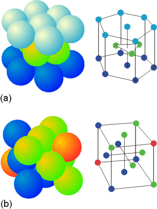
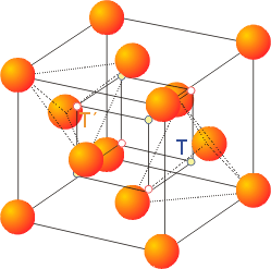
The ABA pattern results in the hexagonal close packed unit cell pictured above (a). The ABC pattern results in a face-centered cubic arrangement, also called a cubic close-packed arrangement, as pictured (b). Either structure contains small holes which account for 26% of the crystal volume. There are two types of holes. Octahedral holes, with a coordination number of 6, lie within two staggered triangular planes of atoms. The octahedral holes of a face centered cube (or cubic close packed unit cell) are illustrated below.
The tetrahedral holes are the small lightly colored circles at the corners of the inner cube. There are two types of tetrahedral holes (yellow and white) indicating two different orientations. For a crystal of n atoms in a close-packed arrangement, there are 2n tetrahedral holes.
Radii of Octahedral and Tetrahedral Holes
The size of an octahedral hole or a tetrahedral hole in a close-packed arrangement will depend on the size of the ion which is close-packed. Assuming the larger ion (usually the anion) is close-packed, the octahedral holes will have a radius of 0.414 times the radius of the larger ion. The tetrahedral holes will have a radius of 0.225 times the radius of the larger ion. In alloys, both metals are in their elemental form, and their atomic radii must be considered. Atomic radii of metals are obtained in pure metal samples as 1/2 the distance between the nuclei of neighboring metal atoms. However, this distance varies with coordination number, with a coordination number of 12 exhibiting metals with their greatest inter nuclear distance. The following table shows the change in atomic radii with coordination number.
For comparison of atomic radii, all are corrected, using the above factors, to a coordination number of 12, even if their typical crystal structure has a lower coordination number. These radii are sometimes referred to as Goldschmidt radii.Coordination # relative radius
12 1.00
8 0.97
6 0.96
4 0.88
Ionic Solids
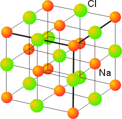
Many ionic structures can be viewed as a close-packed arrangement of the larger ion (usually the anion), with the cations occupying octahedral or tetrahedral holes and distorting the structure so that the anions no longer touch each other. For example, the rock salt structure of NaCl can be viewed as either:
a) as a face centered cubic array of the anions, with the cations occupying the octahedral holes (in the center of each cube and on each edge) or
b) as a face centered array of cations with the anions occupying all the octahedral holesIn either description, each ion has a coordination number of 6, with the unit cell containing an equal number of cations and anions (a 1:1 salt).

Since each ion has four nearest neighbors, the coordination number is 4 in this structure.
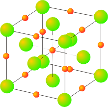
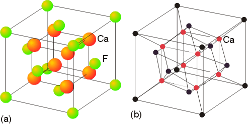
Salts with a 1:2 (or 2:1) stoichiometry sometimes exhibit the fluorite (or antifluorite) structures. The fluorite structure, seen in calcium fluoride, has the calcium ions in a face centered cubic array with the fluoride ions in all (8) of the tetrahedral holes. The fluoride ions have a coordination number of 4, and the calcium ions have a coordination number of 8. Another view of this structure is as a simple cubic arrangement of the anions, with the cations occupying half of the cubic holes.
The antifluorite structure is often seen in salts with the general formula of M2X, such as potassium oxide. The anions are in a face centered cubic arrangement, with the cations in all of the tetrahedral holes.
Copyright ©1998 Beverly J. Volicer and Steven F. Tello, UMass Lowell. You may freely edit these pages for use in a non-profit, educational setting. Please include this copyright notice on all pages.