SERG -- Topics
Finite Element Analysis for the Damage Detection of Light Pole Structures -- A Dynamic Approach
Qixiang Tang and Tzuyang Yu2
1 Doctoral Student, Department of Civil and Environmental Engineering, UML
2 Associate Professor, Department of Civil and Environmental Engineering, UML
Proposed damage detection method
Objective
Failures of aging light poles is a potential threat to public safety and can damage adjacent structures. The need for a reliable and efficient damage detection method is raised in many states including Massachusetts. Fig. 1 shows a fallen light pole covered by media (CBS Boston [Shortsleeve 2012]).
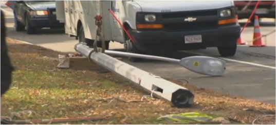
Fig. 1. Fallen light pole in Massachusetts [Shortsleeve 2012]
A research effort was made in SERG to develop a practical solution for the efficient damage detection of aging light poles using numerical simulation (finite element analysis or FEA).
Approach
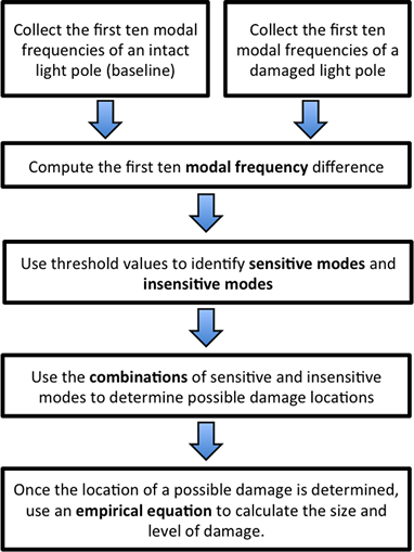
In the mechanical analysis of engineering structures, any change in structural properties (e.g., mass, stiffness and damping) can lead to differences in the dynamic response of structures (i.e., modal frequencies). On the contrary, changes in dynamical responses can be used as indicators for damage detection. In this study, relationships between artificial damages and modal frequencies are determined by investigating the modal frequencies of intact and damaged light pole models using the finite element method (FEM). FE models are built with 5529 C3D8R elements in ABAQUS®. New parameters (sensitive and insensitive modes) are defined and used to evaluate the sensitivity of the first ten modes of FE models. It is found that combinations of sensitive and insensitive modes are unique for each damage location and can be used to locate artificial damages in light pole models. Two empirical equations were developed to quantify damage level and damage size. In this research, intact and artificially damaged light poles are simulated by FEM to study the differences in modal frequencies between intact and damaged FE light pole models. Proposed damage detection methid is described by a research roadmap in Fig. 2.

Fig. 2. Research approach for the damage of light pole structures
Assumptions
- First ten modal frequencies of light pole structures are available. Modal frequencies of light pole sturtcures can be obtained by experimental modal analysis using accelerometers.
- Variation in structural damping is not significant. In this study, emphasis is placed on the global modal frequency change due to the presence of local defects such as steel corrosion and fatique cracking.
- Damages only occur at three prescribed locations (pole-to-baseplate connection, and handhole detail).
- Only one damage in each artificially damaged light pole model is considered. In this study, coupling of
Finite Element Modeling
Each FE light pole model has three components: pole, baseplate and four bolts. Fig. 3 illustrates these components. Connection detail at the baseplate is also provided in Fig. 4.


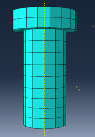
Fig. 3. Three components in a FE light pole model
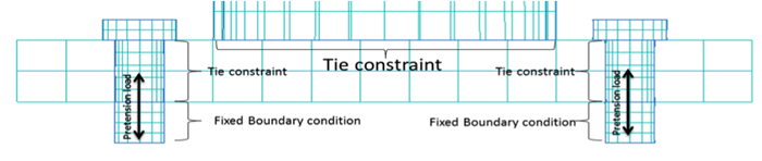
Fig. 4. Connection detail at the baseplate of a FE light pole model
Modeling of Artificial Damages
Damaged FE light pole models are simulated by introducing artificial damages to anintact light pole model. Three damage attributes are defined to characterize any artifical damage;
-
Damage location Lj (j=1,2 or 3, it represents the damage location) (see Fig. 5);
-
Damage size αjA, αjA = [0.2A, 0.4A, 0.6A, 0.8A, 1.0A], where A is the total cross-sectional area (see Fig. 6); and
-
Damage level βjE, βjE = [0.1E, 0.3E, 0.5E, 0.7E, 0.9E], where E is the Young’s modulus of intact material.
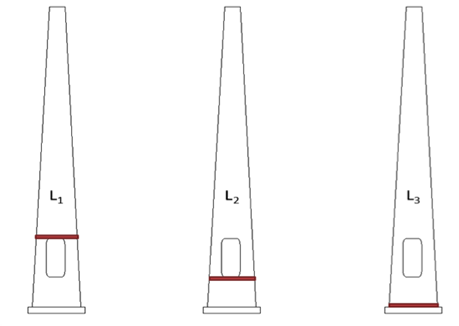
Fig. 5. Three damage locations

Fig. 6. Two example damage sizes
Dynamic Analysis and Definitions
Once the FE models of intact and damaged light poles are created, eigenvalue analysis is performed to extract the first ten modal frequencies of each FE model (Fig. 7). From the values of damage attributes considered in this research, 75 FE models are created.
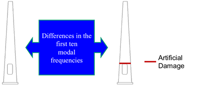
Fig. 7. Two example damage sizes
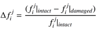
Modal frequency difference (\Delta_f_i^j) at the i-th mode is computed by the following equation:
 (1)
(1)
where f_i^j|_intact = the i-th modal frequency of intact light pole model, and f_i^j|_damaged = the i-th modal frequency of intact light pole model with an artificial damage located at position j.
Sensitive modes are defined by the vibration modes with a modal frequency change greater than t_s:
![]() (2)
(2)
Insensitive modes are defined by the vibration modes with a modal frequency change less than t_i:
![]() (3)
(3)
Sensitive and insensitive modes are identified with the use of t_s and t_i.
Results
-
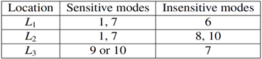
Damage location -- Damage location is determined by the unique combination of identified sensitive and insensitive modes as shown in Table 1.
Table 1.
-
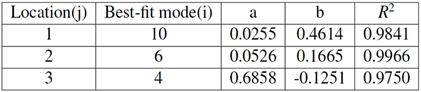
Damage size -- Once damage location is determined, damage size is determined by Eq. (4). Coefficients in Eq. (4) are provided in Table 2.
![]() (4)
(4)
Table 2.
-
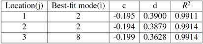
Damage level -- Damage level is determined by Eq. (5). Coefficients in Eq. (5) are provided in Table 3.
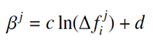 (5)
(5)
Table 3.
References
- Shortsleeve, J., I-team: Aging light poles a safety concern on Mass. roads.http://boston.cbslocal.com/2012/10/31/i-team-aging-light-poles-a-safety-concern-on-mass-roads/, 2012.
- Tang, Q., Finite Element Analysis for the Damage Detection of Light Pole Structures, Master's Thesis, Department of Civil and Environmental Engineering, UML, 2014. (pdf)
- Tang, Q., T. Yu, M. Jen, Finite Element Analysis for the Damage Detection of Light Pole Structures, Proc. SPIE 9437, Structural Health Monitoring and Inspection of Advanced Materials, Aerospace, and Civil Infrastructure 2015, 943711 (1 April 2015); doi: 10.1117/12.2075689. (pdf)