A Little Bit About CNC Machines
Computer Numerical Control (CNC) machines are used heavily in modern manufacturing processes. These machines have been in use since the 1940s, using punched tapes to control conventional milling machines retrofitted with motors. The introduction of this technology allowed the manufacture of more complex shapes. With the proliferation of low cost electronics and personal computing, what was once an expensive technology has rapidly evolved toward more economical desktop sized machines that are readily available to small businesses and hobbyists. The desktop CNC has achieved popularity with the introduction of the do-it-yourself manufacturing and “maker” movement. Because of this, desktop CNCs have morphed into commercial products that are designed for hobbyists.
CNC technology comprises a broad spectrum of various different components, and virtually infinite configuration possibilities. One of the current issues in CNC machines is the knowledge gap between the uniformed beginner and the technical information behind each machine component. CNC technology will be discussed in the following three sections: (1) A general overview of necessary CNC components and parts; (2) Current hobby CNC machines; and (3) Comparison of differences in various different machine options.
CNC mills, Laser cutters, and 3D printers share the same basic setup. They each comprise of three main components: (1) Mechanical hardware; (2) Electronics hardware; and (3) Control Software. The integrating of these three main components yield varying levels of manufacturing tool cost, reliability and accuracy.
Mechanical Hardware
Similar mechanical hardware is used for three-axis CNC mills, laser cutters, and/or 3D printers. The mechanical components move a working tool to a predefined location via a numerical code comprised of a list of coordinates. The method used to move the working tool from coordinate to coordinate is what varies between machines. Motion can be defined using one of four methods: (1) Moving Gantry/Stationary Bed; (2) Moving Gantry/Moving Bed; (3) Stationary Tool/Moving Bed; and (4) Delta Machine.
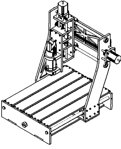
A Moving Gantry/Stationary Bed machine is the most common setup used for three-axis CNC milling machines, laser cutters and some 3D printers. In this configuration, the machine moves the X-Y-Z axis relative to the work bed using Cartesian coordinates. Due to the nature of the design, large and heavy raw materials can be fixed to the bed without impacting the machine’s performance. By design, fixed bed machines have a limited amount of usable space relative to their overall footprint. The motion and usable area is illustrated in Figure 2‑1.
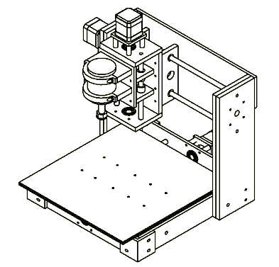
A Moving Gantry/Moving Bed machine is less common in industrial milling applications but is relatively common in hobby milling machines. This approach is also the most common setup for 3D printers. This system also uses Cartesian coordinates to move. A moving bed will move in one-axis and the gantry will provide motion in the remaining two axes. Mills will often move the bed in X- or Y-direction while the moving bed in a 3D printer is usually restricted to the Z-axis. In four- and five-axis machines, one or two rotational beds will be added to increase the machines capabilities. When using a moving bed, the bed must have twice the available distance per axis, which is shown in Figure 2-2.
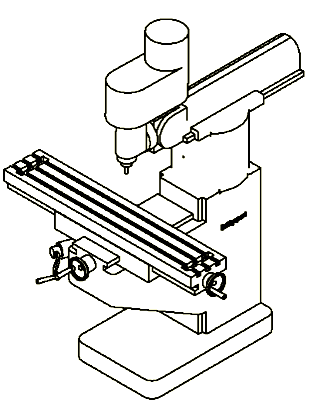
A Stationary Tool/Moving Bed Machine also uses Cartesian coordinates. In these machines, the tool is mounted so that it can only move in the Z-direction and the bed moves in the X- and Y-direction. This system is typically seen on traditional manual mills that have been adapted to become a CNC mill. By not moving the tool in the X- and Y-direction, (most active motions), the spindle can be scaled up to provide increased cutting ability for harder materials. As stated above, the table requires twice the distance in each axis relative to the bed size to utilize the entire working area. The motion of the gantry and working area to foot print can be seen in Figure 2-3.
A moving bed system introduces new design variables over a stationary bed design. When milling a larger/heavier raw material, the weight may affect acceleration and motion performance of the machine. As a result, the machine will experience higher inertial loads on the support bearings, resulting in additional friction and fatigue load cycles. The second variable is the effect of varying mass will vary the momentum of the bed, and ultimately affect the resistance in change of direction. It should be noted that this is only a concern when the weight of the raw material is much greater than the weight of the bed.
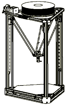
A Delta Motion machine does not use a traditional Cartesian coordinate system like previous three setups but instead uses a triangulation-like process in polar coordinates. The machine uses three independently moved arms that are connected to the tool at one end and each arm is actuated along its own z-axis. This configuration effectively creates three fourbar linkages that move the tool in θ-R-Z coordinates. The delta motion and usable area to foot print comparison can be seen in Figure 2‑4 below.The fourbar linkages create there motion by utilizing the Pythagorean theorem, where the hypotenuse (the arms) are a fixed length and the motion is generated by varying the length of the vertical leg (Z axis) and the horizontal leg. The delta approach offers a relatively simple design but is better suited to additive manufacturing rather subtractive due to its low rigidity.
Please check back soon. More information will be posted in the near future.